Manual Vase Kit (EN)
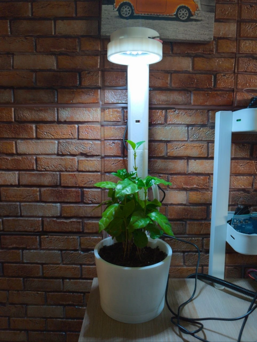
MyDot Vase Kit
Complete setup and operating guide for the examples/MyDotVase sketch included
with the MyDot Arduino library.
The example turns a MyDot carrier into a connected plant-care controller. It reads an analog soil-moisture sensor, controls a pump through the carrier relay, drives the NeoPixels, accepts commands from the Microeden cloud, and stores the light and pump settings in non-volatile memory.
1. Hardware and safety
Required hardware
- Microeden MyDot V1.0 carrier;
- a supported Arduino board (the example is tested with Arduino Nano ESP32);
- AZ-Delivery analog soil-moisture sensor;
- a low-voltage pump and a suitable external pump power supply;
- tubing and a water reservoir;
- a 3D printer for the physical Vase Kit components;
- a Microeden cloud device and Wi-Fi network.
3D-printed components
A 3D printer is required to produce the physical Vase Kit parts, such as the plant container, brackets, sensor supports, and pump/tube holders. The Arduino library contains the firmware example; the mechanical parts must be printed and assembled separately according to the selected Vase Kit design.
STL files to print
Download and print the following files for the Vase Kit assembly:
| File | Component | STL |
|---|---|---|
column.stl |
Standard column section; print the required number of pieces for the plant height | Download STL |
mydot_pump_support.stl |
Pump support | Download STL |
mydot_support.stl |
MyDot case support | Download STL |
vase_bottom.stl |
Water tray / vase bottom | Download STL |
vase_top.stl |
Vase top | Download STL |
The column.stl is a standard-length column section. Print the required number
of identical pieces according to the height of the plant and assemble them
together. Do not scale the file or alter the height of an individual section.
Suggested external materials
The following are the external materials used as references for the Vase Kit prototype:
- Transparent flexible tube – ANOMM
- Self-priming electric pump – RUNCCI-YUN
- Capacitive soil-moisture sensor – AZ-Delivery
- Male-to-male jumper wires
These links are reference products, not library dependencies or guaranteed compatibility statements. Before assembly, verify the tube inner diameter, the pump voltage/current, the pump flow rate, and the relay/driver ratings for your specific hardware.
Power requirements
Power the carrier through its external DC jack when using the relay, pump, NeoPixels, or fan driver. USB power alone is not sufficient for the carrier output stages. Use the voltage range specified for the carrier and the pump driver, and verify the polarity before connecting power.
The pump must be powered through the carrier relay or an appropriate external driver. Never connect a pump or motor directly to an Arduino GPIO.
Soil sensor warning
Power the AZ-Delivery soil sensor from 3.3 V, not 5 V. A 5 V analog output can exceed the input range of the selected board and may damage it.
| Sensor connection | MyDot/Nano connection |
|---|---|
VCC |
3V3 |
GND |
GND |
AO / analog output |
A0 |
Nano ESP32 pin mapping
The MyDot library uses the carrier pin aliases below when an Arduino Nano ESP32 is selected:
| Function | Nano ESP32 alias |
|---|---|
| Soil sensor analog input | A0 |
| Button A | A7 |
| Button B | D4 |
| Relay | D2 |
| NeoPixels | D3 |
| SD card chip select | D10 |
The library supports both Arduino pin numbering and By GPIO number (legacy) mode. The recommended setting is the normal Arduino pin numbering mode; use the legacy option only when the rest of the project requires it.
2. Installing the example
- Install MyDot from the Arduino IDE Library Manager, or copy the library into the Arduino libraries directory.
- Install the dependencies declared in
library.propertiesif the IDE does not install them automatically. - Select Arduino Nano ESP32 and the correct serial port.
- Open File > Examples > MyDot > MyDotVase.
- Open the
microeden_secrets.htab and replace the placeholders locally:#define SECRET_WIFI_SSID "YOUR_WIFI_SSID" #define SECRET_WIFI_PASSWORD "YOUR_WIFI_PASSWORD" #define SECRET_DEVICE_ID "YOUR_DEVICE_ID" #define SECRET_DEVICE_TOKEN "YOUR_DEVICE_TOKEN"Never commit real Wi-Fi credentials or cloud tokens.
- Connect the external carrier power supply, connect the board by USB, and upload the sketch.
- Open the Serial Monitor at 115200 baud.
The ESP32 cloud connection uses the bundled ISRG Root X1 certificate. No insecure TLS switch is required.
3. What the sketch does
The source is:
The sketch performs these operations:
- Initializes the MyDot peripherals and the persistent-state backend.
- Restores the saved light mode, light state, brightness, and pump duration.
- Starts Wi-Fi and the MQTT cloud connection.
- Reads and averages eight soil ADC samples.
- Publishes soil, pump, light, and event telemetry.
- Handles cloud commands, slider events, and local buttons.
- Runs the pump timer and Wi-Fi/MQTT reconnection logic continuously.
The main loop must keep calling dot.run(). Do not replace it with long
blocking delays.
4. Local controls
- Button A toggles the lights on and off.
- Button B cycles through the five light modes:
coolWhite,warmWhite,growVegetative,growBloom, andgrowFull.
The button actions save their state immediately.
5. Cloud controls
The cloud command field is normally named content.
Commands
| Command | Effect |
|---|---|
pump |
Starts one timed pump cycle using the saved duration. |
lights_on |
Turns the NeoPixels on using the saved mode and brightness. |
lights_off |
Turns the NeoPixels off without losing brightness. |
lights_warm |
Selects warm white. |
lights_cool |
Selects cool white. |
grow_veg |
Selects vegetative grow mode. |
grow_bloom |
Selects bloom grow mode. |
grow_full |
Selects full-spectrum grow preset. |
lights_mode |
Uses an additional numeric mode field from 0 to 4. |
The old continuous on and off pump commands are intentionally not handled.
The pump is activated only by pump and stops automatically.
Slider widgets
Slider messages use the compact format key_value in the cloud content field.
| Slider key | Example message | Range | Stored |
|---|---|---|---|
brightness |
brightness_128 |
0–255 | Yes |
pumpDuration |
pumpDuration_5 |
1–60 seconds | Yes |
The slider value is consumed once as an event. A telemetry/state echo from the cloud cannot be mistaken for a new command and cannot reset the value to zero.
Telemetry fields
The sketch publishes these fields:
| Field | Meaning |
|---|---|
soilRaw |
Averaged ADC reading from A0. |
soilPercent |
Calibrated soil percentage. |
pumpOn |
Read-only current relay state. |
pumpActivations |
Number of pump activations since boot. |
pumpDuration |
Configured duration for the next activation. |
lightsOn |
Current light state. |
lightMode |
Current mode name. |
lightModeIndex |
Current mode index, 0–4. |
brightness |
Current NeoPixel brightness, 0–255. |
event |
Reason for the last telemetry message. |
Typical event values include periodic, pump, pumpStop, pumpBusy,
pumpCooldown, brightness, pumpDuration, lightsOn, and lightsOff.
6. Pump timing and safety
The duration slider is limited in code to 1–60 seconds. The default is two
seconds. When pump is received:
- the relay is enabled;
pumpOnbecomestrue;pumpActivationsis incremented;- a
pumptelemetry message is sent; - the relay is disabled automatically after the configured duration;
- a
pumpStoptelemetry message is sent.
There is also a one-minute cooldown measured from the start of the previous
activation. A second command received while the cycle is active produces
pumpBusy; a command received during the cooldown produces pumpCooldown.
This prevents a faulty widget, repeated MQTT messages, or an automation loop
from continuously restarting the pump.
The cooldown is runtime protection. It is reset when the board reboots; the configured duration itself remains persistent.
Water management
Before starting an irrigation cycle, check that there is water available in the tray/reservoir. Check the tray after watering and empty it periodically, so water does not remain stagnant or overflow. The tray should be inspected and emptied regularly as part of normal maintenance.
For the 3D-printable Vase Kit, start with a pump duration of one second at most. The printed kit has a small water capacity, so longer cycles can quickly overfill the tray. If the pump is used with a different system or a larger pot, adjust the irrigation duration to the pot size, tubing, pump flow rate, and drainage. Test the selected duration with supervision before enabling automatic operation.
7. Soil calibration
The example defines:
const int SOIL_RAW_DRY = 3000;
const int SOIL_RAW_WET = 1300;
The default conversion assumes the sensor ADC value decreases as the soil gets
wetter. soilPercentFromRaw() maps the dry value to 0% and the wet value to
100%, then clamps the result to 0–100.
To calibrate your sensor:
- Read
soilRawwith the probe in dry soil and record the value. - Read it in well-watered soil and record the value.
- Replace
SOIL_RAW_DRYandSOIL_RAW_WETin the sketch. - Recompile and upload.
Do not power the sensor from 5 V while calibrating.
8. Persistent state
The state record contains:
lightsOn;mode;brightness;pumpDurationSeconds.
Storage is selected automatically by board architecture:
- Nano ESP32: ESP32
Preferences/ NVS; - Nano RP2040 Connect with the Mbed core: Mbed KVStore;
- RP2040 or Nano 33 IoT cores with EEPROM support: EEPROM.
The record includes a magic value, version, and checksum. The current record version is 4. Records from version 3 are migrated for the light fields and use the default two-second pump duration until a new value is saved.
Changing the light state, brightness, or pump-duration slider saves immediately. Telemetry is delayed briefly only to avoid flooding the cloud while a slider is being dragged.
9. Serial diagnostics
Use the Serial Monitor at 115200 baud. Useful messages include:
Restored light state...;Restored pump duration...;Pump duration from cloud...;Pump request ignored: a timed cycle is already active;Pump request ignored: cooldown active...;Telemetry - ...;MyDot: MQTT connected.and reconnection messages.
The Display example is intended for OLED diagnostics. MyDotVase uses the
Serial Monitor so all soil, cloud, pump, and persistence messages remain visible
while the plant controller is running.
10. Troubleshooting
The sketch compiles but the pump does not run
- Verify the carrier external power supply is connected.
- Check that the pump has its own suitable supply.
- Check the relay/driver wiring and common ground.
- Confirm that the Serial Monitor reports
pumpand thenpumpStop. - Check whether the one-minute cooldown is active.
The pump cannot be started again
This is expected during the active cycle and for up to 60 seconds after its
start. Wait for the cooldown or inspect the pumpCooldown telemetry event.
The slider appears not to change
- Confirm the dashboard key is exactly
brightnessorpumpDuration. - Confirm the incoming content is
brightness_<value>orpumpDuration_<seconds>. - Confirm the value is within the documented range.
- Watch the Serial Monitor for the corresponding
from cloudmessage.
The lights are off after a reboot
- Check the restored
lightsOn,brightness, andlightModemessages. - Ensure the carrier is powered through the external jack.
- Verify the NeoPixel data pin is the carrier
D3alias on Nano ESP32. - Make sure the installed library is the same version as the uploaded sketch.
Soil values are unsafe or inverted
- Verify the sensor is powered at 3.3 V.
- Confirm
AOis connected toA0. - Calibrate
SOIL_RAW_DRYandSOIL_RAW_WETfor the actual soil and probe.
11. Recommended test sequence
- Run the sketch with the pump disconnected and verify
soilRawtelemetry. - Toggle the lights with Button A.
- Cycle modes with Button B.
- Change
brightnessand verify the value is saved after a reset. - Set
pumpDurationto a short test value such as 1–2 seconds. - Send
pumponce and verify automatic stop telemetry. - Send another
pumpimmediately and verify it is rejected by the cooldown. - Connect the pump only after the relay and timing behavior are correct.